Chapter 2
Class diagrams
2.1 Packages, classes, attributes and operations
2.1.1 To define a package
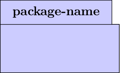
You can define a package with the umlpackage environment:
Both options x and y allow to define the package position in the figure. The default value for both of them is 0.
Option type
- When a package contains classes and sub-packages, its dimensions automatically fit to its content.
- You can define as many packages as you want in a figure.
- For an empty package (that contains no class), you can use a shortcut command: umlemptypackage that takes the same arguments and options as the umlpackage environment
2.1.2 To define a class
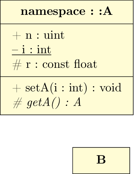
You can define a class with the umlclass command:
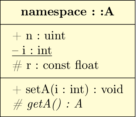
The class name is defined with the first argument or the umlclass command. As you can see, you can use double dots in it.
The attributes of a class are defined with the second argument of the umlclass command. You write the attributes list using \\ as a delimiter. The operations of a class are defined with the third argument of the umlclass command.
To define a static attribute or a static operation, you can use the umlstatic command. In a similar way, the umlvirt command is used to define a virtual operation.
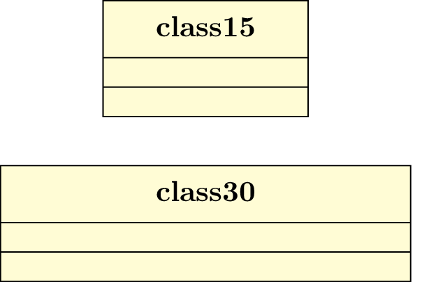
For empty classes (that contains no attributes and no operations), you can use a shortcut command umlemptyclass:
![]()
You may also prefer drawing a single rectangle node instead of a 3 parts rectangle node. In this case, you may use the simple option of umlclass or the shortcut command umlsimpleclass that also takes only the class name for argument and the same options as the command umlclass:
The umlclass command (and its shortcuts) also takes options.
Name of the node defining a class
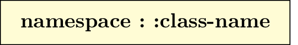
To name a class, you may want use special characters, such as _, or double dots (:) when giving namespace. Internal mechanism of TikZ-UML name the class node with the class name. But to name a TikZ node, backslashes and double dots are forbidden. As far as double dots are concerned, string substitutions are done on the class name to define the node name. But for _, it does not work so easily. That is why you can directly name a node with the option name:
To define coordinates of the class node
Both options x and y allow to define the class position in the figure. 2 cases: if the class is defined inside a package, the class position is relative to the package; on the contrary, the class position is relative to the figure. The default value for both options is 0.
To define the width of a class
The default width of a class is 10ex. You can use the width option to specify an other value:
To define type and tagged values of a class
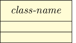
There is different types of classes: class, interface, typedef, enum. You can specify it with the type option (the default value is class):
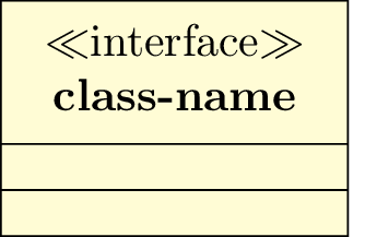
 The type is written between ≪ and ≫ above the class name, excepted the class type (default behavior), and
the abstract type, where the class name is written in italic style instead:
The type is written between ≪ and ≫ above the class name, excepted the class type (default behavior), and
the abstract type, where the class name is written in italic style instead:
Shortcuts exist for each value of the type option: umlabstract, umltypedef, umlenum, umlinterface. For
these shortcuts, option type is forbidden.
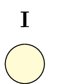
You can also draw interfaces with a circular node. To do so, you can use the simple option to the
umlinterface command, or use the shortcut umlsimpleinterface
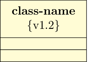
To add tagged values to a class, you can use the option tags:
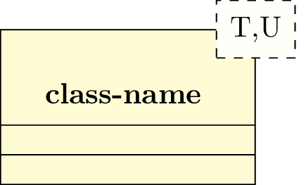
To specify template parameters
For a template class, you can use the template option to specify the template parameters list:
2.2 To define a relation between classes
2.2.1 General command
Each class or package is draw as a node sharing the same name. To define a relation between two classes, you just need to specify the source class name, the target class name and a set of options specific to the relation:
From a UML semantic point of view, there are 12 different relations. Every type of relation is defined in TikZ-UML :
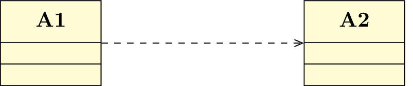
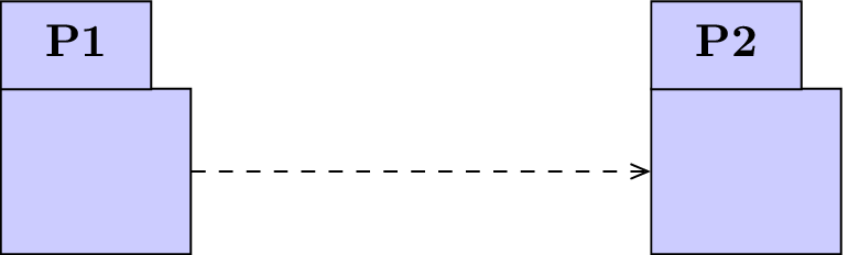
- A dependency:
- You can use the umldep command
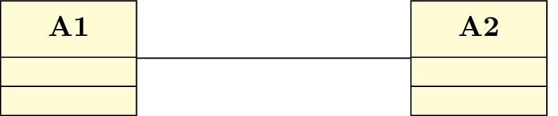
- An association:
- You can use the umlassoc command
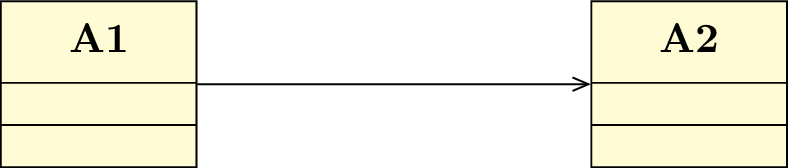
- A unidirectional association:
- You can use the umluniassoc command
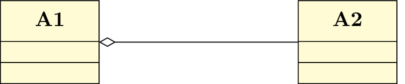
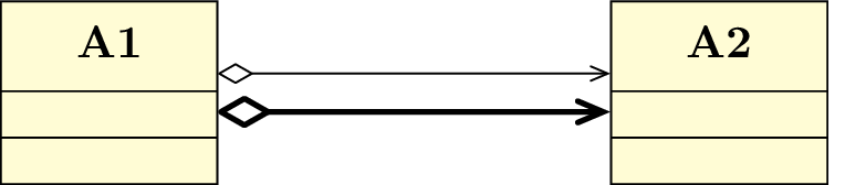
- An aggregation:
- You can use the umlaggreg command
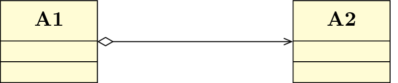
- A unidirectional aggregation
- You can use the umluniaggreg command
- A composition:
- You can use the umlcompo command

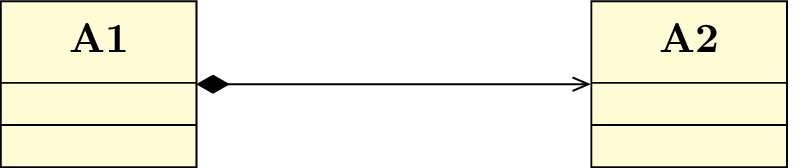
- A unidirectional composition:
- You can use the umlunicompo command
- An import:
- You can use the umlimport command
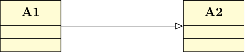
- An inheritance:
- You can use the umlinherit command
- An implementation:
- You can use the umlimpl command

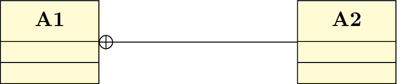
- A nesting:
- You can use the umlnest command
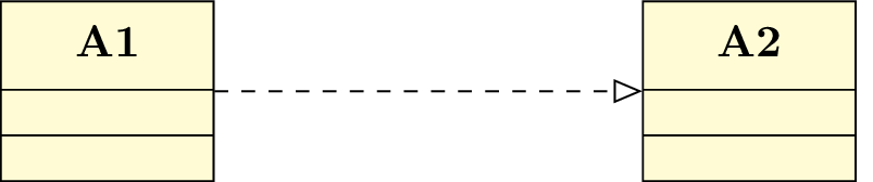
- A realization:
- You can use the umlreal command
These 12 shortcuts are based on the same scheme (the umlrelation command) and take theoretically the same set of options. Nevertheless, some options concern only part of them.
2.2.2 To define the geometry of a relation
As you may have seen in previous examples, you can specify the geometric shape of a relation with the geometry option. It needs a value among the following list: - - (straight line), -| (horizontal then vertical), |- (vertical then horizontal), -|- (horizontal chicane) ou |-| (vertical chicane). These values are very inspired from TikZ philosophy.
It seems that this option is used very often. That is why a shortcut of the umlrelation command has been defined each possible value of the geometry option:
- umlHVrelation:
- shortcut of umlrelation with geometry=-|
- umlVHrelation:
- shortcut of umlrelation with geometry=|-
- umlHVHrelation:
- shortcut of umlrelation with geometry=-|-
- umlVHVrelation:
- shortcut of umlrelation with geometry=|-|
For each of these 4 shortcuts, the geometry option is forbidden.
There is no shortcut for the value - -: this is the default value for the umlrelation command.
2.2.3 To adjust the geometry of a relation
When the geometry is built with 2 segments, you can define the coordinates of the auto-built point, named control node. Then, instead of using umlrelation, you should use the umlCNrelation command, or one of its 12 shortcuts:
When the geometry is built with 3 segments, the relative position of the middle segment between classes is defined by the midlle of the classes nodes. You can adjust this parameter with the weight option:
In some cases, this option is not very convenient, because it needs to compute the option value to give. There is another possibility by uusing the arm1 and arm2 options, that control the size of the first and last segment respectively. Let’s see the 2 following examples using respectively the weight option and the arm1 option:

The arm1 and arm2 options also take negative values. How does it work then ? A positive value means an arm oriented to the right direction (to the right or to the top), whereas a negative valuemeans an arm oriented to the opposite direction, that allows you to draw other 3-segments relations:
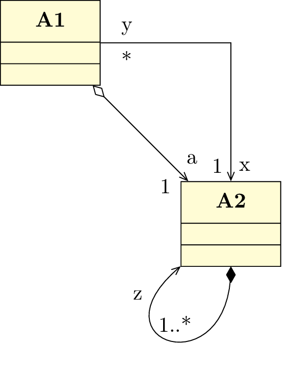
2.2.4 To define informations about attributes of a relation
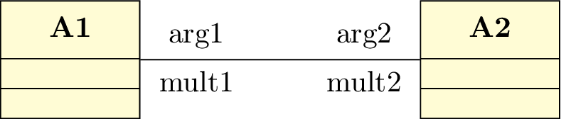
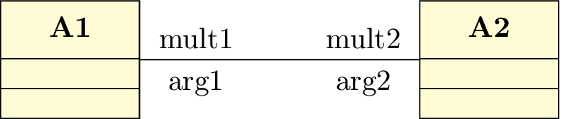
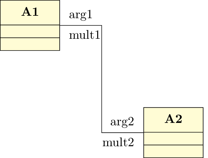
A relation means a dependency between two classes and represents an attribute in most of the cases. You can define its name with the arg1 option or the arg2 option, and its multiplicity with the mult1 option or the mult2 option:
For unidirectional relations, you should use only arg2 and mult2 options. That is why shortcuts have been defined, namely the arg option and the mult option respectively.
In addition, when you define the name and the multiplicity of an attribute, you may prefer use the all-in-one following options attr1, attr2 and attr:

This has an advantage: the semantic of the two values has disappeared and you can switch them for convenience:
2.2.5 To place information about attributes of a relation
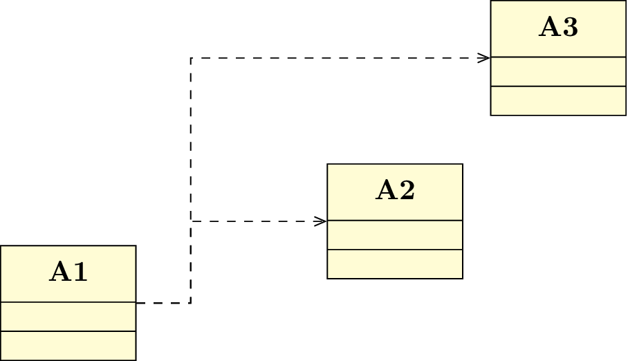
You can place information seen in previous section with the following options: pos1, pos2 and pos. The umlrelation command determine by itself if name and multiplicity should be written on left and right or on top and bottom of the arrow, according to the geometry and their placement. For those who know TikZ enough, the mechanism is based on auto and swap options.
You may have noticed that the range of values of the position depends on the number of segments composing the arrow. For a straight line, position has to be between 0 (source class) and 1 (target class). If there are 2 segments, then position has to be between 0 et 2 (target class), the value 1 corresponding to the control node. Otherwise, position has to be between 0 et 3, values 1 and 2 corresponding to the first and second control node respectively.
2.2.6 To adjust the alignment of information about attributes of a relation
Name and multiplicity of an attribute, when they are written on top and bottom of the relation, are centered by default. You can define an other alignment. The options align1, align2 and align are used to have ragged right or ragged left text:
2.2.7 To define and place the stereotype of a relation
The stereotype of a relation is a keyword contained between ≪ and ≫. You can define it with the option stereo and place it with the option pos stereo.
2.2.8 To modify the anchor points of a relation
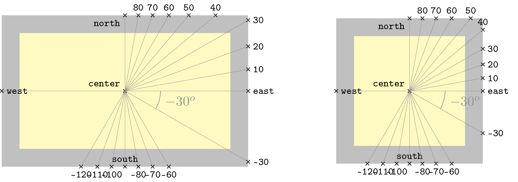
The default behavior of a relation is to start from the center anchor of the source class node and to end to the center anchor of the target class node. You can adjust this with the options anchor1 and anchor2.

You give angular values in degree and they can be negative. The internal mechanism of TikZ uses modulos. The value 0 is east, 90 is north, 180 (or -180) is west, et 270 (or -90) is south. The following figure illustrates this option and its angular meaning on 2 examples of rectangular nodes, (class nodes for instance). You can notice that border anchors (to use TikZ vocabulary) depend on node dimensions.
You will very often define anchor1 and anchor2 simultaneously. In this case, you can use the all-in-one option anchors:
2.2.9 To define a recursive relation
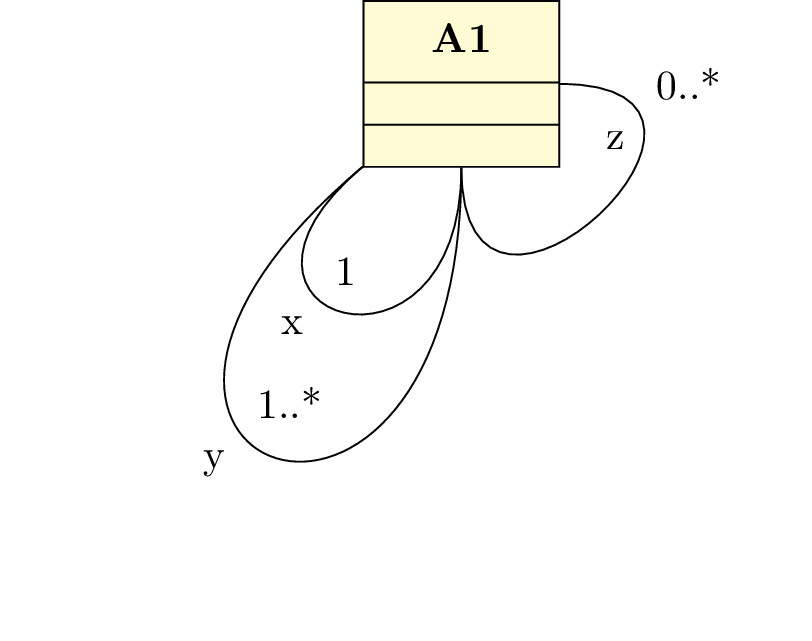
You can define recursive relations, namely a relation from a class to itself. Then, the geometry option is disabled, but 3 specific options are available: angle1 determines the start angle, angle2 determines the end angle, and loopsize controls the size of the loop.

When you use recursive relations, you will notice that you will need the 3 options simultaneously. This is the reason why a compact form is defined, the recursive option, and the following syntax:
2.2.10 Name of auto-built points of a relation
In order to understand the purpose of giving a name to a relation, one should explain how arrows are defined.
To build an arrow, we need to define control nodes, and a name for each one. The only way to identify a relation is to give a name using a id counter. This counter is incremented each time we define a relation in a picture. Let’s suppose the relation has the id i. The name of the relation, called relname in the following, is: relation-i
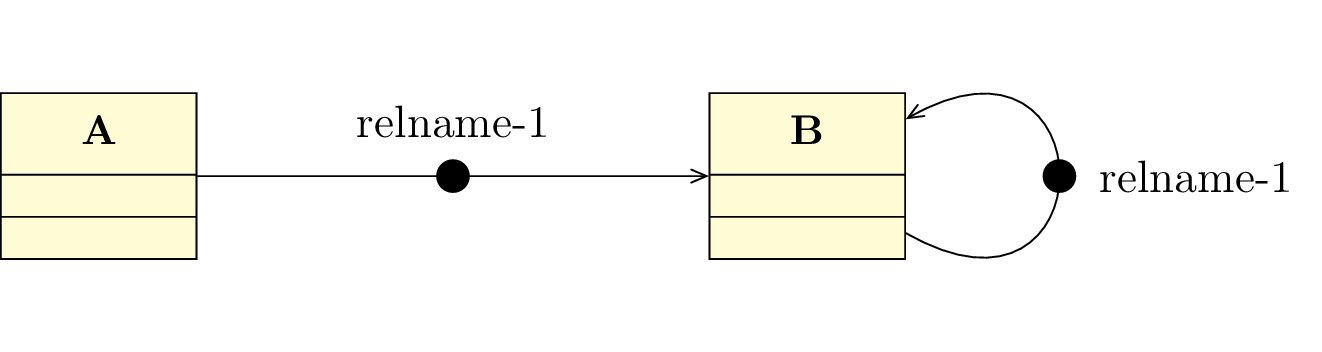
The first defined node is the middle of the class nodes. It is called relname-middle. To simplify, we will not deal with the placement of the argument and its multiplicity here. So, there are 3 cases:
- If the arrow is a straight line or a recursive line, it is renamed in relname-1.
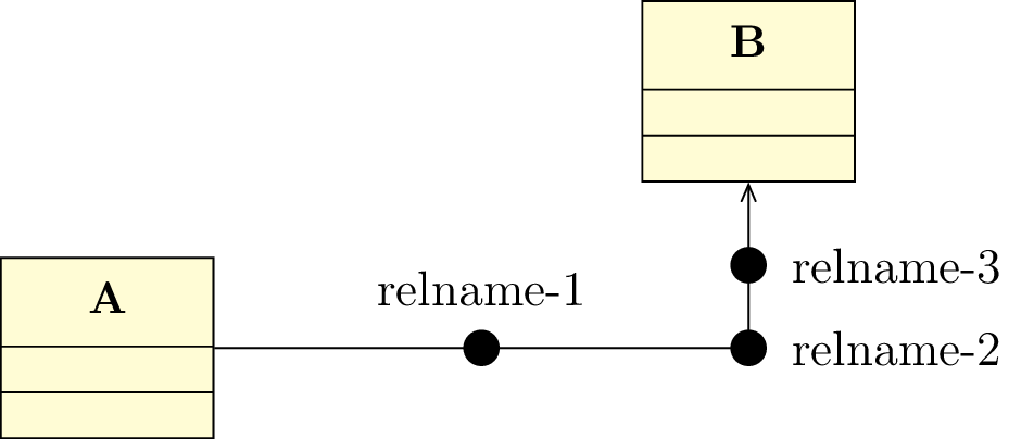
- If the arrow has one right angle, the node placed at the angle is named relname-2, that is enough to draw
the arrow. 2 other nodes are defined, placed at the middle of each arc and named respectively relname-1
and relname-3.
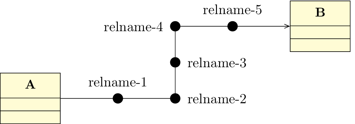
- If the arrow has 2 right angles, they are defined with relname-middle, that is enough to draw the
arrow. Nodes placed at the angles are named respectively relname-2 and relname-4. 3 other
nodes are defined, at the middle of each arc, named respectively relname-1, relname-3, and
relname-5.
This default behavior is not easy to use, because the value of the counter is not defined by the user, and depends on the order of definition of the relations in the picture. This is the reason why you can define relname thanks to the name option. In the two following sections, you will see when this option is useful.
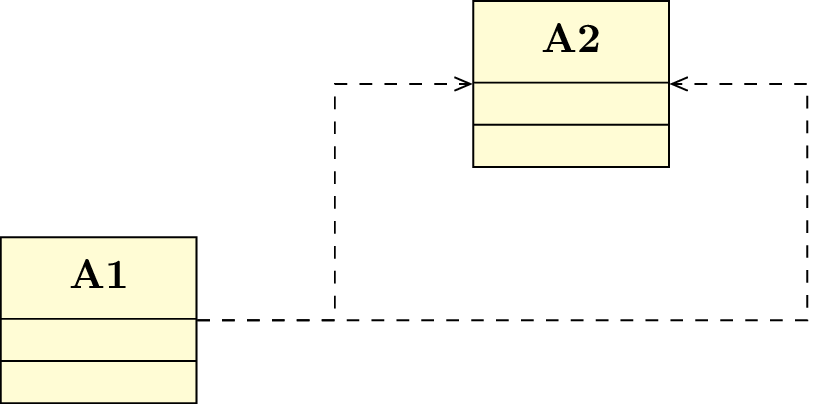
2.2.11 To draw an intersection point between relations
When you draw a diagram, it occurs that relations cross other ones or share arcs. Let’s take two crossing arrows. Can both start points go graphically to both end points ? If yes, you will want to draw a point at the intersection of the arrows, and this point should be a control node of one the the relations. To define the point, you can use the umlpoint command.
2.2.12 Advanced styling of a relation
On a relation, you can use every TikZ option, thickness options for instance:
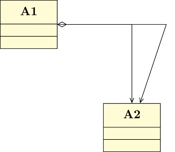
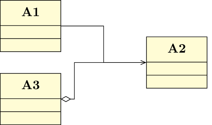
2.2.13 N-ary associations
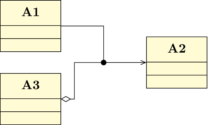
Sometimes, you need to draw a relation between more than two classes, namely a n-ary association. To do so, you have to draw the main node of such a relation, ans link it to every class it has to be linked:
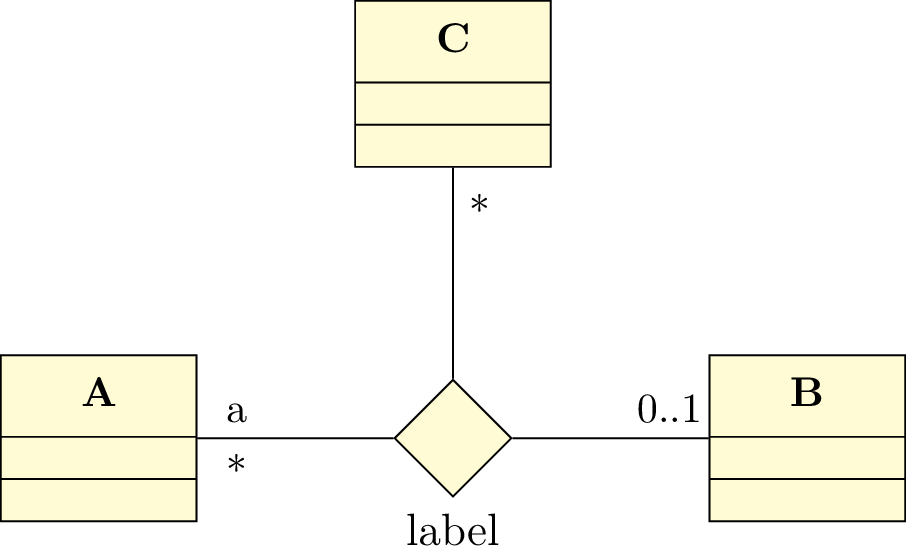
The umlNarynode command accepts the following options:
- width: to set the width of the node
- name: to give a name to the node and use it in others macros
- below, below left, left, above left, above, above right, right, below right: to place the label of the n-ary node. Contrary to their equivalents in TikZ , these options has to be used without values. The default is above.
To use advanced positioning, do not forget to load TikZ library positioning
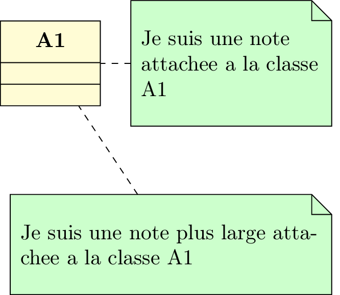
2.3 Comments / constraints note
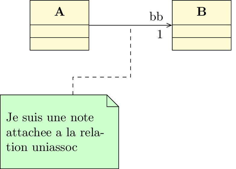
A note is a text comment attached to a class or a relation. The umlnote command needs the name of the node as argument:
Here again, you can give the name of a control node of a relation to attach the note. Giving a name to the relation will be very useful:
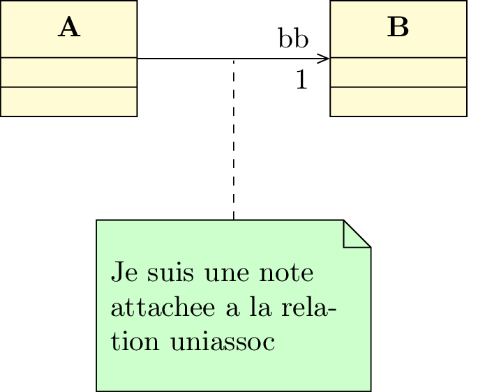
Notes have 2 uses: comments and contraints (generally in OCL format).
The umlnote command has the following options:
- x, y
- These 2 options define the coordinates of the note.
- width
- This option defines the width of the note. For TikZ users, it encapsulates the text width option
- weight, arm, anchor1, anchor2, anchors
- These options has the same behavior as for umlrelation, arm being equivalent to arm1, namely attached to the note.
For a note, you can also use the geometry option, as for umlrelation. Default value is –. For other values, aliases have been defined: umlHVnote, umlVHnote, umlHVHnote and umlVHVnote.
For each of these aliases, the geometry option is forbidden.
2.4 Association class
Drawing an association class is very easy with TikZ-UML . It is just a class and a dependency between this class and a built point of another relation. The umlassocclass makes it for you:
As the command is like a class and a relation, you can use the following options: x, y, width (default is 10ex), type (default is class), template coming from the umlclass environment, and name, geometry (default is - -), weight, arm, anchor1, anchor2, and anchors coming from the umlrelation command.
2.5 Advanced features for positioning
umlpackage, umlclass and their aliases, umlnote and umlassocclass can accept every option key defined for nodes in TikZ . In this section, you will see how some of them can be used for advanced features.
2.5.1 Horizontal and vertical alignment
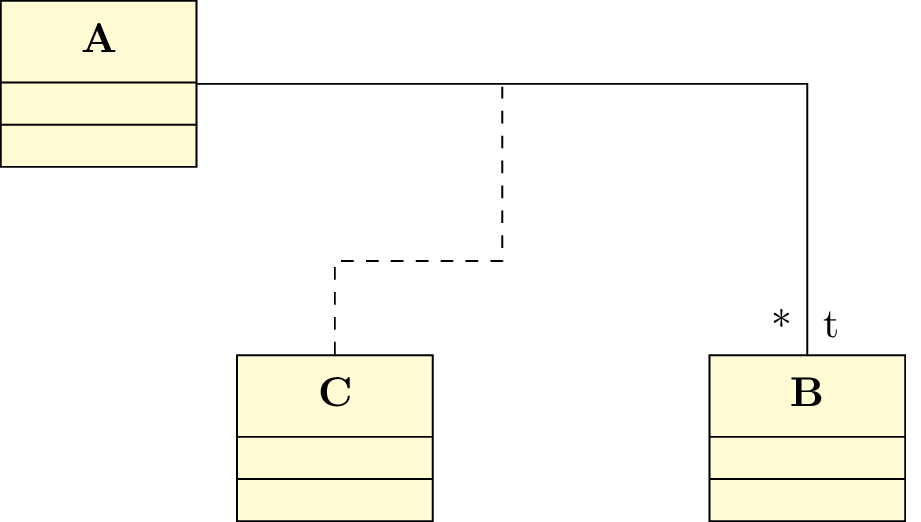
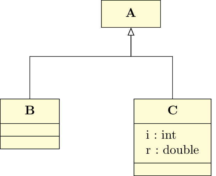
In a class diagram, classes have different width and height. For a graphical purpose, you may want to align them horizontally or vertically. Let’s take the following example:
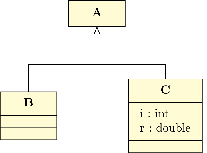
The y coordinate defines the center of the class node. It will be better in this example to have classes B and C top-aligned. A solution is to define manually the y value for C, but it is not very convenient. You may prefer use the anchor option. If you specify anchor=north, the y coordinate will define the top center anchor of the node, instead of the center. You may take a look at the differences between both codes.
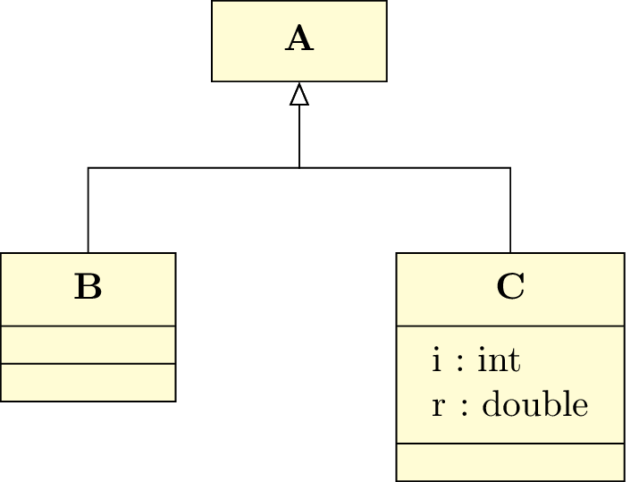
In a similar way, you may use anchor=east to right align classes, anchor=west to left align classes or anchor=south to bottom align classes.
For empty packages, association classes and notes, you can also use the mechanism.
2.5.2 Relative positioning
Using the x-y coordinate system may be very hard in big diagrams, when you have to change position of elements in order to fit the diagram to the page. Relative positioning may be useful in this case, namely advanced syntax of options above, left, below, right, above left, below left, below right and above right provided by the TikZ library positioning.
Let’s take the previous example, you can define B by its cordinates (-2,-2) or by saying that B is 2cm below and 2cm left of A. You can also define C by saying it is 4cm right of B. Notice that because of the top alignment of B and C, the latter is defined 4cm right of B.north.
For empty packages, association classes and notes, you can also use the mechanism.
2.6 To change preferences
Thanks to the tikzumlset command, you can change default preferences for packages, classes and notes. The available options are:
- text:
- allows you to set default text color for every drawn object (=black by default),
- draw:
- allows you to define default edge color for every drawn object (=black by default),
- fill class:
- allows you to define the default background color of a class node (=yellow!20 by default),
- fill template:
- allows you to define the default background color of a template node (=yellow!2 by default),
- fill package:
- allows you to define the default background color of a package (=blue!20 by default),
- fill note:
- allows you to define the default background color for a note (=green!20 by default),
- font:
- allows you to define the default font style for every drawn object (=\small by default).
- x:
- allows you to set the default first coordinate (=0 by default)
- y:
- allows you to set the default second coordinate (=0 by default)
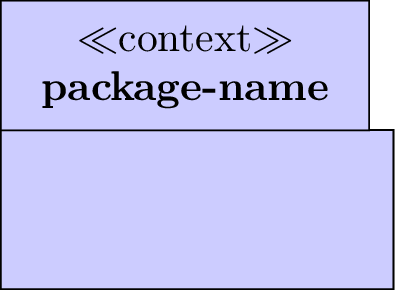
- package type:
- allows you to set the default package type (=package by default)
- class width:
- allows you to set the default class width (=10ex by default)
- simple interface width:
- allows you to set the default width of a simple interface (=4ex by default)
- class type:
- allows you to set the default class type (=class by default)
- narynode width:
- allows you to set the default n-ary node width (=6ex by default)
- relation geometry:
- allows you to set the default geometry of a relation (=– by default)
- relation angle1:
- allows you to set the default angle1 of a relation (=-30 by default)
- relation angle2:
- allows you to set the default angle2 of a relation (=30 by default)
- relation loopsize:
- allows you to set the default loopsize of a relation (=3em by default)
- relation weight:
- allows you to set the default weight of a relation (=0.5 by default)
- relation pos1:
- allows you to set the default pos1 of a relation (=0.2 by default)
- relation pos2:
- allows you to set the default pos2 of a relation (=0.8 by default)
- relation pos stereo:
- allows you to set the default pos stereo of a relation (=0.5 by default)
- note width:
- allows you to set the default note width (=3cm by default)
Furthermore, relation commands has the style option taking a TikZ style name as value.
Let’s see the definition of the umlinherit command:
You can easily define a command on this model by defining a particular style.
2.7 Examples
2.7.1 Example from introduction, step by step
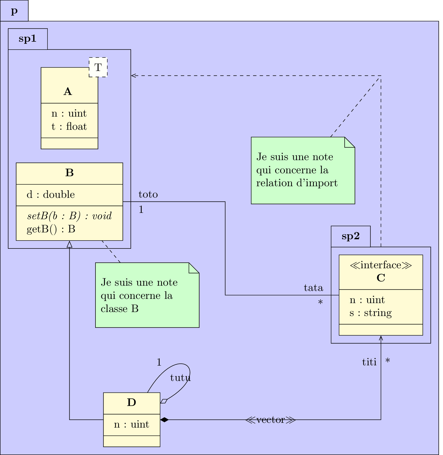
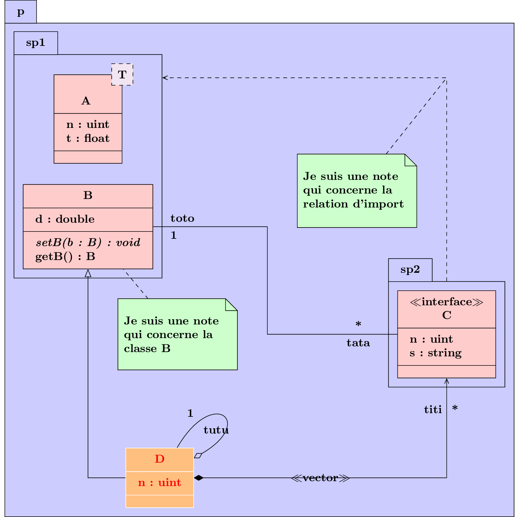
We will now build step by step the picture seen in introduction to understand the behavior of each used command.
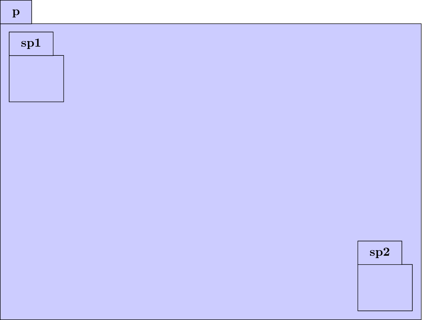
Definition of packages p, sp1 and sp2
The package p is placed at (0,0) (default), and the sub-packages sp1 and sp2 respectively at (0,0) and (10,-6).
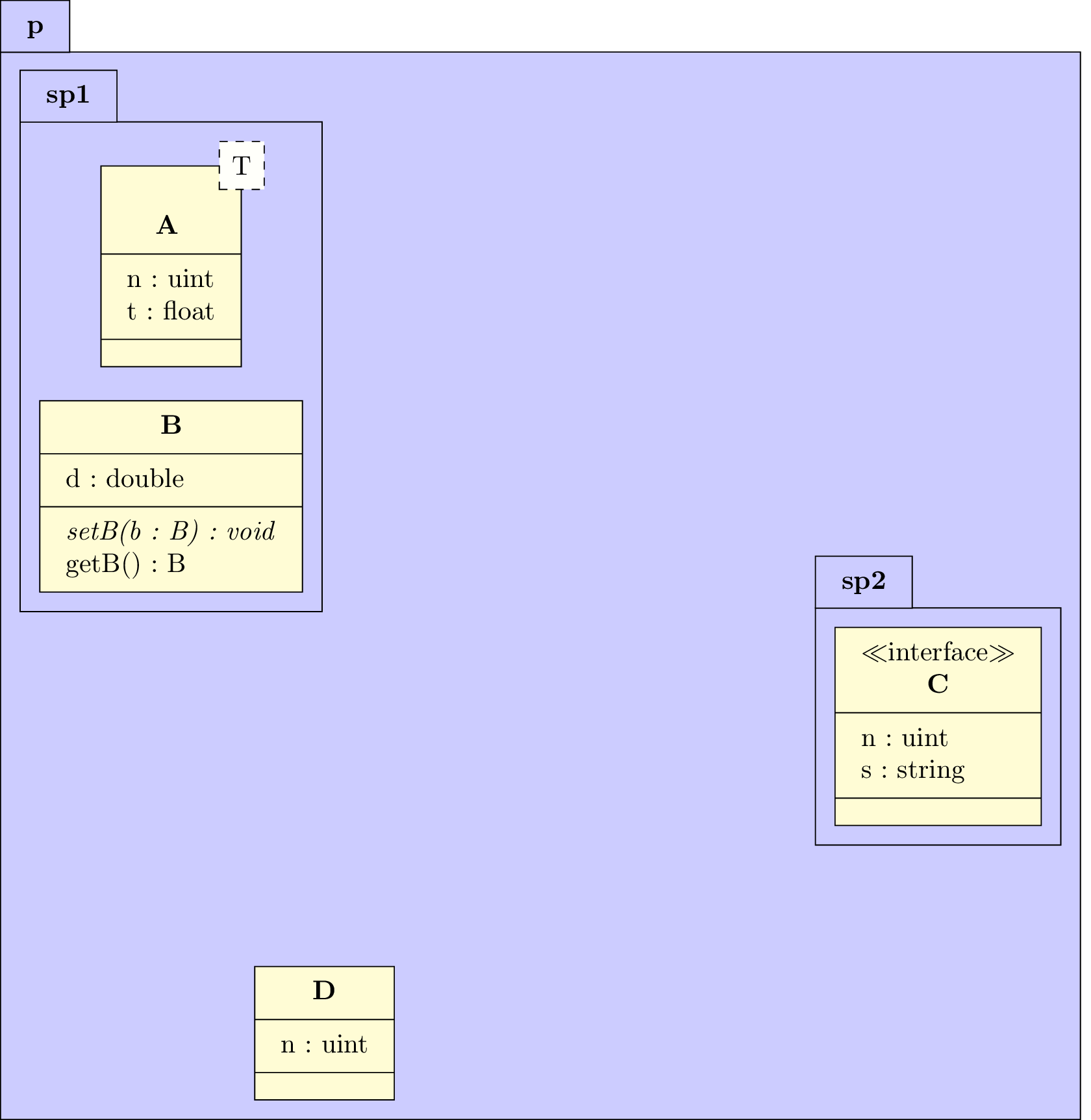
Definition of classes A, B, C, D and their attributes and operations
The class A is placed at (0,0) in the sub-package sp1 and has a template parameter: T. The class B is placed 3 units below A, still in the sub-package sp1. The interface C is placed at (0,0) in the sub sp2. The class D is placed at (2,-11) in the package p.
Class A has two attributes. Class B has one attribute and two operations (one is virtual). Class C has two attributes. Classe D has one attribute.
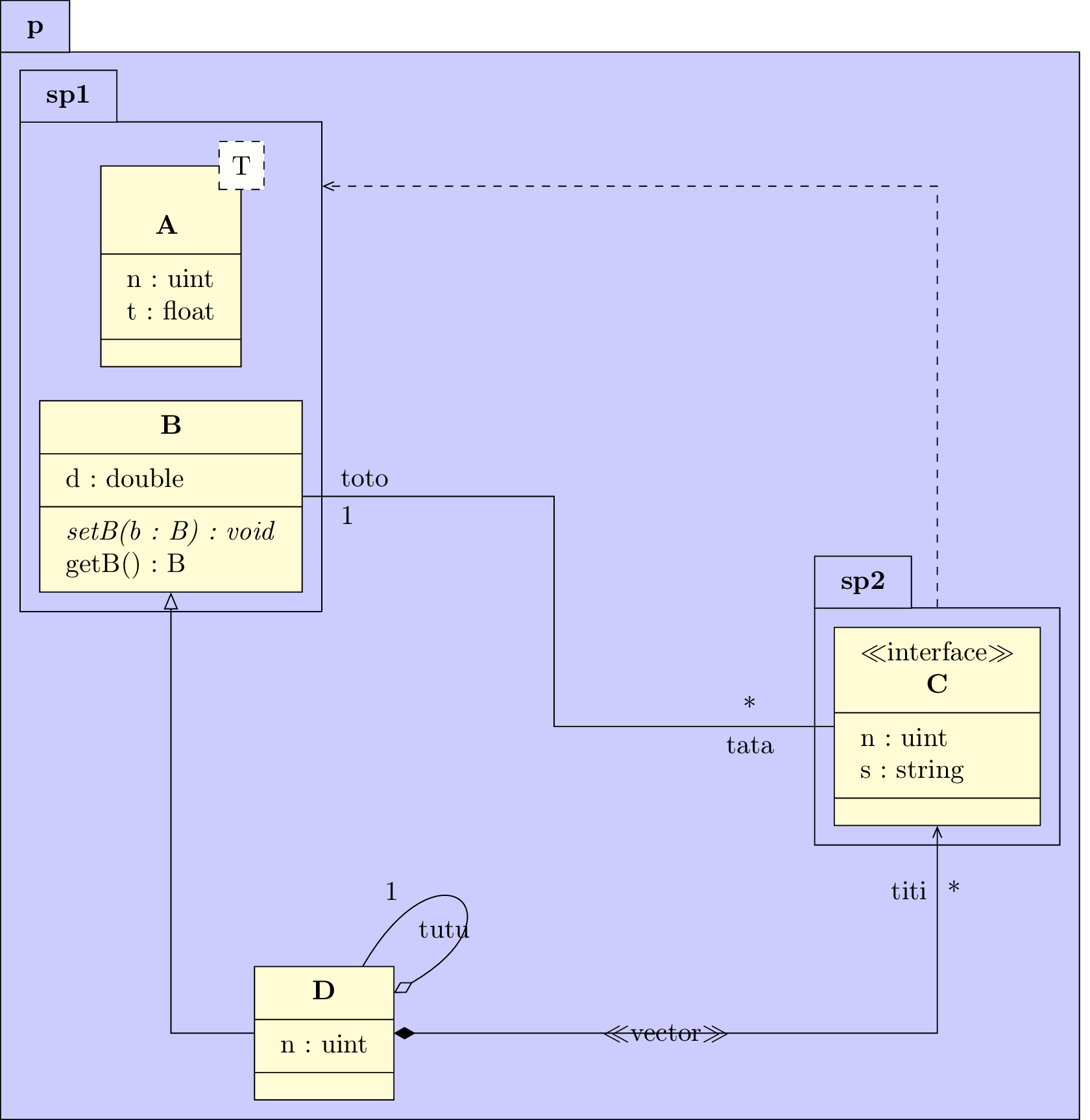
Definition of relations
We define an association between classes C and B, a unidirectional composition between classes D and C, an import relation named "import" between sub-packages sp2 and sp1 (with modification of anchors), a recursive aggregation on class D and an inheritnce between classes D and B. On thses relations, we will specify argument names and multiplicities. You can notice the value given to place these elements on each arrow according to the geometry.
...
Definition of notes
We add a note attached to class B and a note attached to the import relation.
...

Setting style
We illustrate the use of the tikzumlset command by changing colors associated to class and font. We can also change colors of a given class with draw, text and fill options.
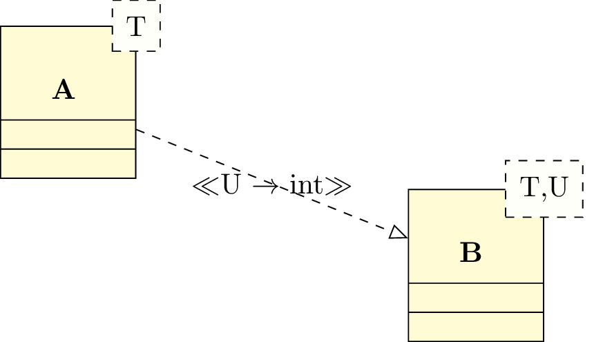
2.7.2 To define a specialization of a class
A specialization of a classe is an inheritance from a templace class in which one of the template parameters is defined. To draw this relation, you will use the umlreal command , and its stereo option:
2.8 Priority rules of options and known bugs
- The geometry option has always the priority on the others options. It means for instance that if it has a non-default value, then angle1, angle2 and loopsize options, defining recursive relations, will be ignored.
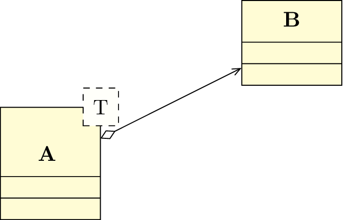
- As far as a template class is concerned, there are cases in which a relation about it will not be
drawn correctly, as in the picture below, where the aggregation symbol is hidden by the template
parameter:
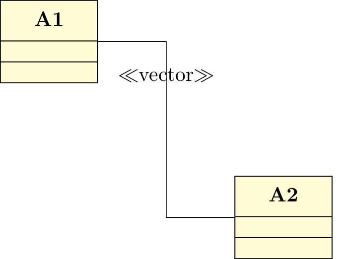
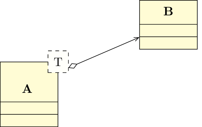
To solve this problem, you van link the arrow between the template part of class A and class B, by adding the suffix -template and adjusting the start anchor (the -30 value is correct here):
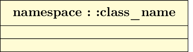
- If you define a class with a name having the: character in it – typically when you give the namespace of
the class – it may have a conflict with the french (or frenchb or francais) option of the babel package.
Indeed, these options add a white-space before the: character if the writer forgot it, that is
a problem for the access operator::. If we take the example of class definition, we should
obtain:
The solution is to use a specific macro given by these options of babel package you have to use in the preamble of your document:
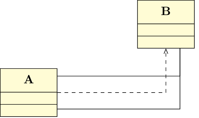
- The automatic placement of argument names and multiplicity on a relation can be surprising when
you can to deactivate it. Let’s take the example shown in introduction. If we focus on the
association relation and its attributes
toto andtata ,toto is above,tata is below. If we justify to the right thetata attribute (and change its position to 0.1), positions oftata and its multiplicity exchange.