Chapter 5
Sequence diagrams

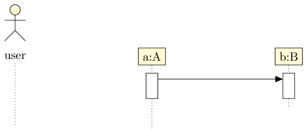
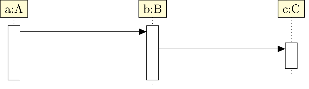
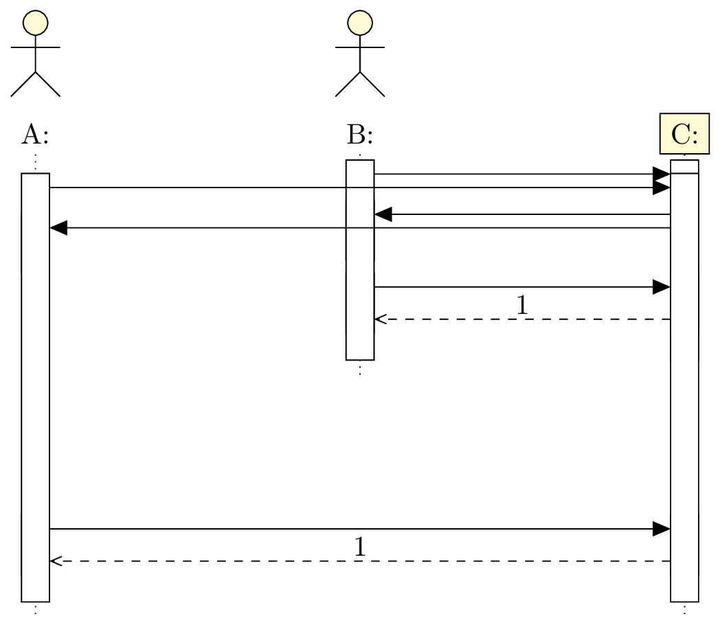
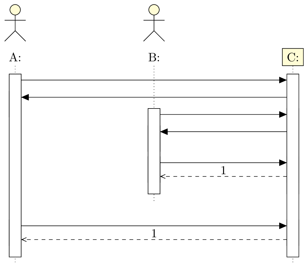
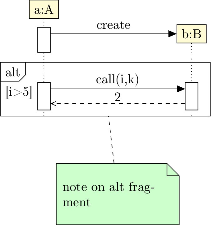
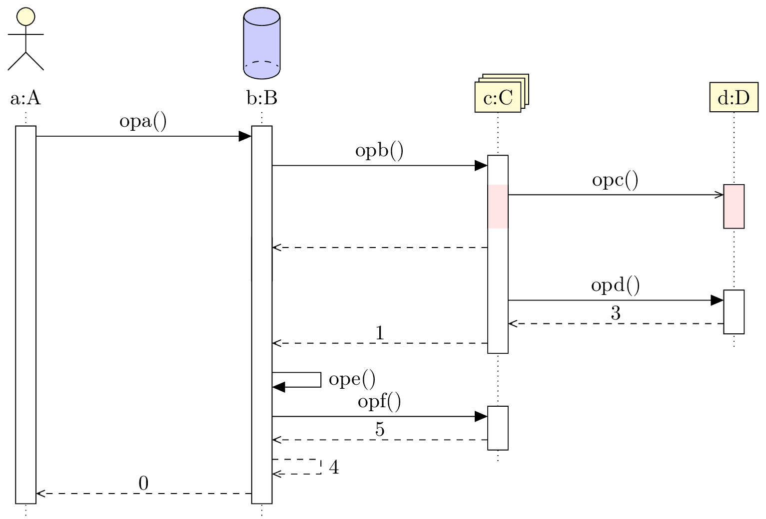
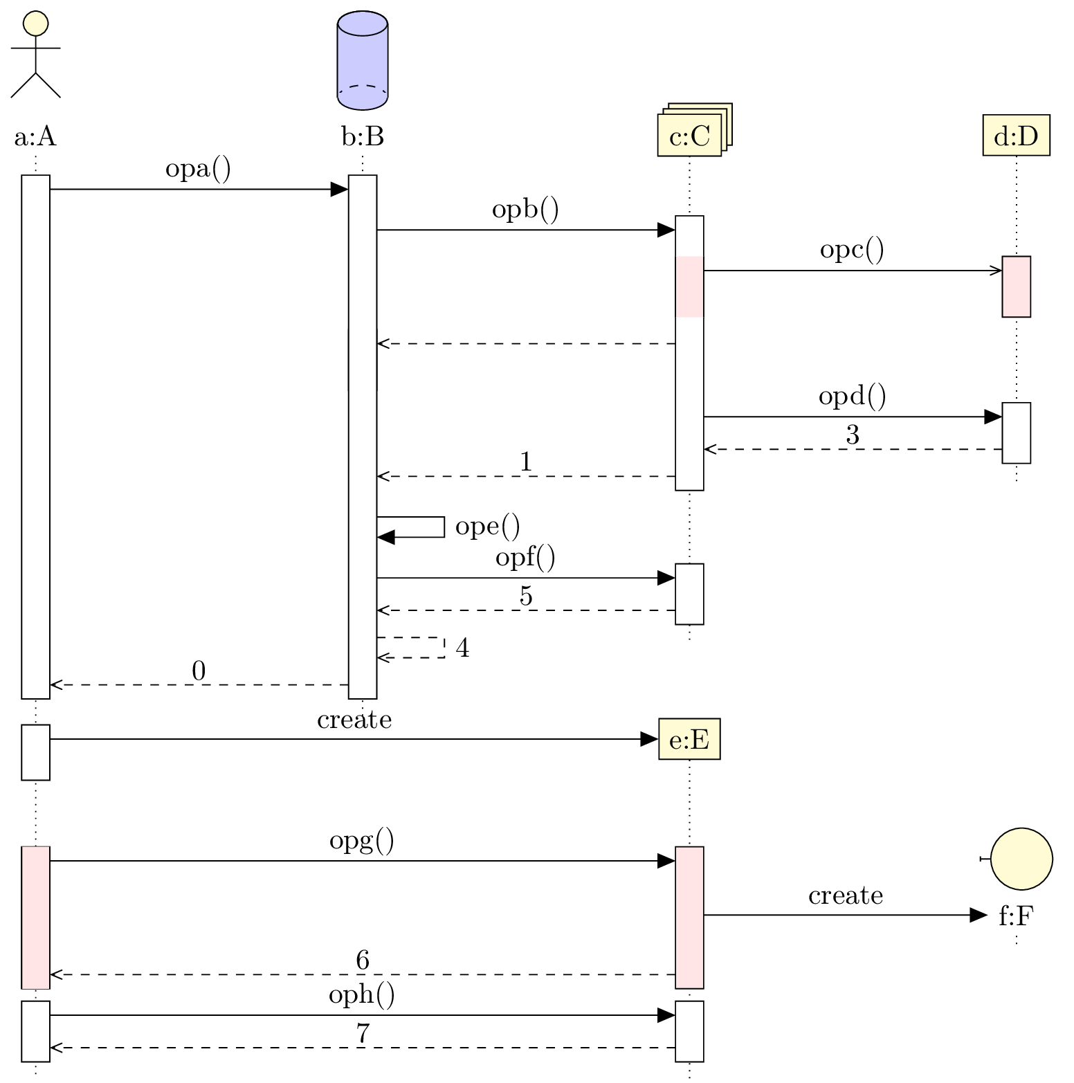
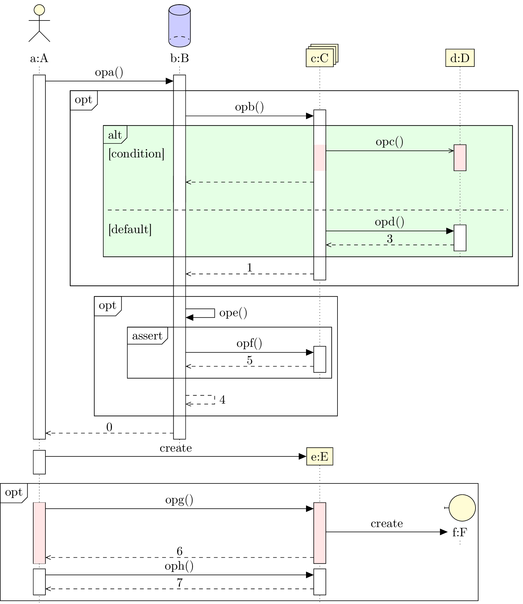
Here is an example of sequence diagram you can draw:

pict

Now, we will talk about elements that compose such diagrams.

5.1 To define a sequence diagram

Here is the main difference from previous diagrams: to define a sequence diagram, you have to use a umlseqdiag environment. Its aim is to initialise some global variables and to draw the lifelines of each object in the diagram. You have to understand that commands and environments you will use to define a sequence diagrams place the elements (calls, objects, …) automatically. We will talk about that in more details later.

5.2 To define an object

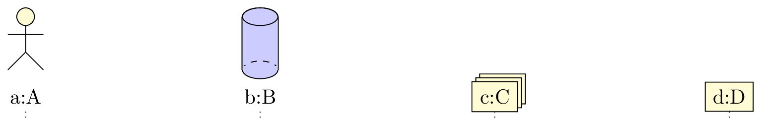
5.2.1 Types of objects

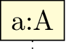
You can define an object with the umlobject command:

 \begin{tikzpicture}  \begin{umlseqdiag}  \umlobject{a}  \end{umlseqdiag}  \end{tikzpicture}

pict

The default type is a class instance. You can give the class name with the class option (empty by default).

 \begin{tikzpicture}  \begin{umlseqdiag}  \umlobject[class=A]{a}  \end{umlseqdiag}  \end{tikzpicture}

pict

On the contrary, you may want to hide the double dots and not giving a class:

 \begin{tikzpicture}  \begin{umlseqdiag}  \umlobject[no ddots]{a}  \end{umlseqdiag}  \end{tikzpicture}

pict

The stereo option allows to set the type of object. It needs one of the following values: object (default value), actor, entity, boundary, control, database, multi. The last six are drawn in the following picture, from left to right and top to bottom:

 \begin{tikzpicture}  \begin{umlseqdiag}  \umlactor[class=B]{b}  \umlentity[x=2, class=C]{c}  \umlboundary[x=4, class=D]{d}  \umlcontrol[x=0, y=-2.5, class=E]{e}  \umldatabase[x=2, y=-2.5, class=F]{f}  \umlmulti[x=4, y=-2.5, class=G]{g}  \end{umlseqdiag}  \end{tikzpicture}

pict

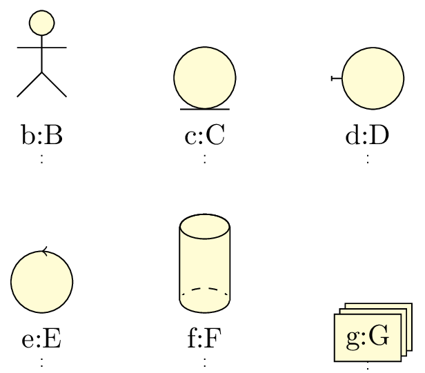
UML objects may be used in other contexts than class instances. Then, the colon symbol shown in an object may not be necessary. For this purpose, you may use the umlbasicobject command.

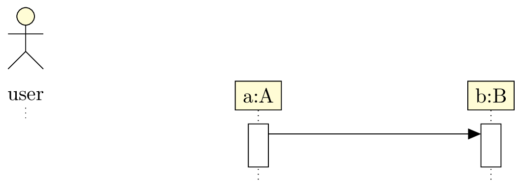
5.2.2 Automatic placement of an object

Both options x and y allows to place an object. You only have to use them if the automatic placement does not do what you need. Its behavior is the following:

Unless the width of the object is too large, a shift of 4 is enough. If not, you use the x option.

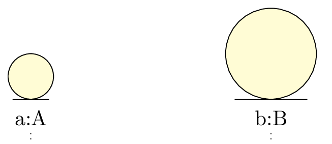
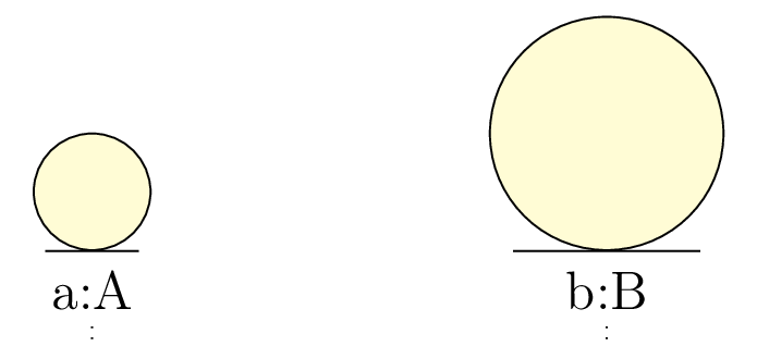
5.2.3 To scale an object

The scale option of the umlobject command allows to scale an object, its symbol and its font size:

 \begin{tikzpicture}  \begin{umlseqdiag}  \umlobject[class=A, stereo=entity]{a}  \umlobject[x=4, scale=2, class=B, stereo=entity]{b}  \end{umlseqdiag}  \end{tikzpicture}

pict

 \tikzumlset{font=\large}  \begin{tikzpicture}  \begin{umlseqdiag}  \umlobject[class=A, stereo=entity]{a}  \umlobject[x=4, scale=2, class=B, stereo=entity]{b}  \end{umlseqdiag}  \end{tikzpicture}

pict

5.3 To define a function call

Function calls are the core of sequence diagrams. Then, we need a motor either smart enough to propose a satisfacting default behavior, either easy enough to parametrize.

From a technical point of view, and I open here a parenthesis, there are two ways to implement function calls:

  1. Either we use the nodal matrix structure of TikZ . The advantage is to work on a pre computed nodal grid and then to place elements of a sequence diagram easily (and fast for compilation) with exactly one counter.
  2. Either we use an automatical positioning of nodes with a set of coordinates, here the time instant, that allows total freedom for the user and make its work easier.

I chose the second way, to keep the philosophy used to implement the other diagrams in this package. Indeed, if the lack of a grid needs a more accurate computation core, and as a result more compilation time, you can define most of the elements very easily, such as constructor calls, drawn according to the standard. That is different from others UML softwares I used before. I close the parenthesis.

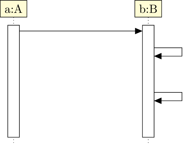
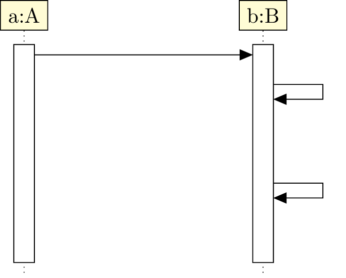
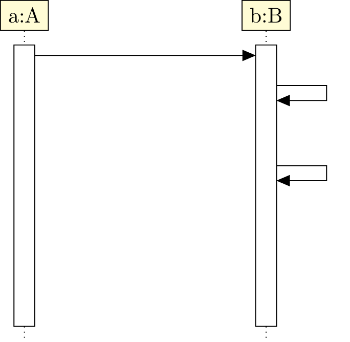
5.3.1 Basic / recursive calls

You can define a function call with the umlcall environment. Of course, you can define umlcall environments in other ones:

 \begin{tikzpicture}  \begin{umlseqdiag}  \umlobject[class=A]{a}  \umlobject[class=B]{b}  \umlobject[class=C]{c}  \begin{umlcall}{a}{b}  \begin{umlcall}{b}{c}  \end{umlcall}  \end{umlcall}  \end{umlseqdiag}  \end{tikzpicture}

pict

You have to give the name of the source object and the name of the destination object. If you give the same name as source and destination, you define a recursive call. In this case, you may prefer use an alias, the umlcallself environment:

 \begin{tikzpicture}  \begin{umlseqdiag}  \umlobject[class=A]{a}  \umlobject[class=B]{b}  \begin{umlcall}{a}{b}  \begin{umlcall}{b}{b}  \end{umlcall}  \begin{umlcallself}{b}  \end{umlcallself}  \end{umlcall}  \end{umlseqdiag}  \end{tikzpicture}

pict

Of course, you can define umlcallself inside umlcallself and umlcall:

 \begin{tikzpicture}  \begin{umlseqdiag}  \umlobject[class=A]{a}  \umlobject[class=B]{b}  \begin{umlcall}{a}{b}  \begin{umlcallself}[op=c1, return=0]{b}  \begin{umlcallself}[op=c2, return=true]{b}  \end{umlcallself}  \end{umlcallself}  \end{umlcall}  \end{umlseqdiag}  \end{tikzpicture}

pict

5.3.2 To place a call

The dt option allows to place a function call on a lifeline, relatively to the last call drawn on this lifeline. It has no default value. Its unit is ex. The default behavior is to shift the call you define to avoid overwriting between to consecutive calls:

 \begin{tikzpicture}  \begin{umlseqdiag}  \umlobject[class=A]{a}  \umlobject[class=B]{b}  \begin{umlcall}{a}{b}  \begin{umlcall}{b}{b}  \end{umlcall}  \begin{umlcallself}[dt=5]{b}  \end{umlcallself}  \end{umlcall}  \end{umlseqdiag}  \end{tikzpicture}

pict

pictpictpict Do not forget that using option dt means relatively to the last call defines on the lifeline.

 \begin{tikzpicture}  \begin{umlseqdiag}  \umlactor{A}  \umlactor{B}  \umlobject{C}  \begin{umlcall}{A}{C}  \begin{umlcall}{C}{A}  \end{umlcall}  \begin{umlcall}{B}{C}  \begin{umlcall}{C}{B}  \end{umlcall}  \begin{umlcall}[return=1]{B}{C}  \end{umlcall}  \end{umlcall}  \begin{umlcall}[dt=20, return=1]{A}{C}  \end{umlcall}  \end{umlcall}  \end{umlseqdiag}  \end{tikzpicture}

pict

Both calls between B and C are first ones, so they are drawn on top of the lifeline. However, you want that they are drawn below the first call between A and C. By using option dt, you can do it:

 \begin{tikzpicture}  \begin{umlseqdiag}  \umlactor{A}  \umlactor{B}  \umlobject{C}  \begin{umlcall}{A}{C}  \begin{umlcall}{C}{A}  \end{umlcall}  \begin{umlcall}[dt=10]{B}{C}  \begin{umlcall}{C}{B}  \end{umlcall}  \begin{umlcall}[return=1]{B}{C}  \end{umlcall}  \end{umlcall}  \begin{umlcall}[dt=20, return=1]{A}{C}  \end{umlcall}  \end{umlcall}  \end{umlseqdiag}  \end{tikzpicture}

pict

You can also set spaces for recursive calls with the padding option. It set the space just below the recursive call:

 \begin{tikzpicture}  \begin{umlseqdiag}  \umlobject[class=A]{a}  \umlobject[class=B]{b}  \begin{umlcall}[padding=10]{a}{b}  \begin{umlcall}{b}{b}  \end{umlcall}  \begin{umlcallself}{b}  \end{umlcallself}  \end{umlcall}  \end{umlseqdiag}  \end{tikzpicture}

pict

pict padding can also takes negative values, to fix for instance position of a call too far away for the previous one.

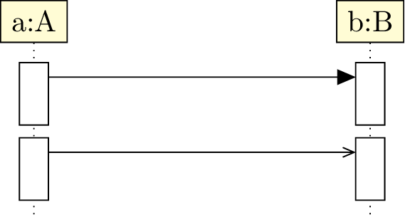
5.3.3 Synchron / asynchron calls

The type option allows to tell if the call is synchron (default value) or asynchron:

 \begin{tikzpicture}  \begin{umlseqdiag}  \umlobject[class=A]{a}  \umlobject[class=B]{b}  \begin{umlcall}[type=synchron]{a}{b}  \end{umlcall}  \begin{umlcall}[type=asynchron]{a}{b}  \end{umlcall}  \end{umlseqdiag}  \end{tikzpicture}

pict

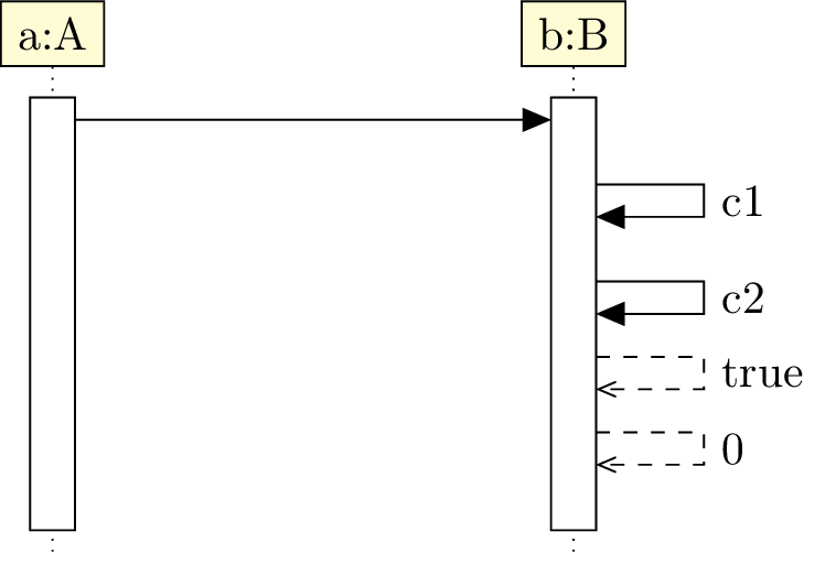
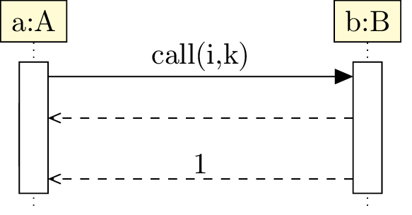
5.3.4 Operation, arguments and return value

You can give the function name in a call and its arguments with the op option:

 \begin{tikzpicture}  \begin{umlseqdiag}  \umlobject[class=A]{a}  \umlobject[class=B]{b}  \begin{umlcall}[op={call(i,k)}]{a}{b}  \end{umlcall}  \end{umlseqdiag}  \end{tikzpicture}

pict

pict Beware of the braces, so as to the comma between i and k is deactivated as an option delimiter. WIthout them, there will be a compilation error.

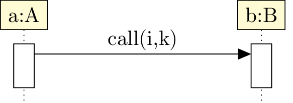
You can also set the return value with the return option, with the same warning:

 \begin{tikzpicture}  \begin{umlseqdiag}  \umlobject[class=A]{a}  \umlobject[class=B]{b}  \begin{umlcall}[op={call(i,k)}, return=2]{a}{b}  \end{umlcall}  \end{umlseqdiag}  \end{tikzpicture}

pict

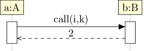
In this case, the return arrow is drawn with the return value above. You can draw the return arrow without giving a return value. For this, there is the with return option:

 \begin{tikzpicture}  \begin{umlseqdiag}  \umlobject[class=A]{a}  \umlobject[class=B]{b}  \begin{umlcall}[op={call(i,k)}, with return]{a}{b}  \end{umlcall}  \end{umlseqdiag}  \end{tikzpicture}

pict

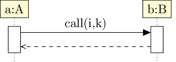
In some cases, the call may have multiple return arrows. To draw an additionnal return arrow, you can do as follows:

 \begin{tikzpicture}  \begin{umlseqdiag}  \umlobject[class=A]{a}  \umlobject[class=B]{b}  \begin{umlcall}[op={call(i,k)}, return=1]{a}{b}  \begin{umlcall}[type=return]{b}{a}  \end{umlcall}  \end{umlcall}  \end{umlseqdiag}  \end{tikzpicture}

pict

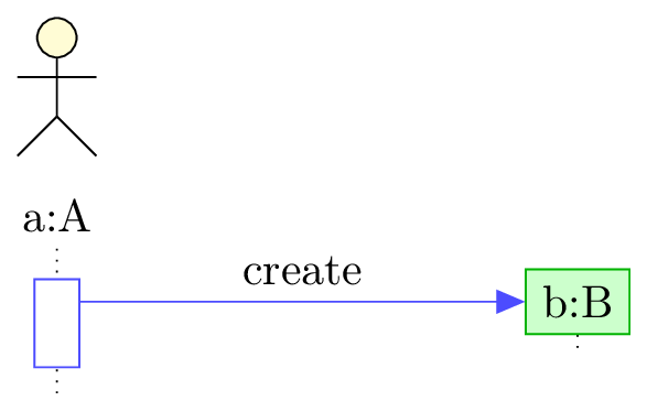
5.3.5 To define a constructor call

Constructor calls are special function calls, insofar as they build a new object. They are not messages between two lifelines, but between a lifeline and an object.

To define a constructor call, you can use the umlcreatecall command:

 \begin{tikzpicture}  \begin{umlseqdiag}  \umlobject[class=A]{a}  \umlcreatecall[class=B]{a}{b}  \begin{umlcall}[op={call(i,k)}, return=2]{a}{b}  \end{umlcall}  \end{umlseqdiag}  \end{tikzpicture}

pict

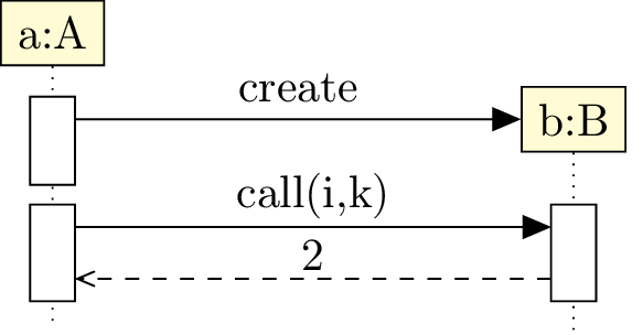
You can notice that everything behave normally after a constructor call.

As an object builder, the umlcreatecall command has class, stereo and x options.

As a function call, it has the dt option.

5.3.6 To name a call

The name option allows to give a name for a function call. It is not useful actually, insofar as this option was added for the definition of combined fragments, but as you will see, combined fragment does not use this feature. Maybe this option will be used for future developments of the package.

5.4 To define a combined fragment

Combined fragments are the second family of elements in a sequence diagram, with the function calls. You can define them with the umlfragment environment:

 \begin{tikzpicture}  \begin{umlseqdiag}  \umlobject[class=A]{a}  \umlcreatecall[class=B]{a}{b}  \begin{umlfragment}  \begin{umlcall}[op={call(i,k)}, dt=7, return=2]{a}{b}  \end{umlcall}  \end{umlfragment}  \end{umlseqdiag}  \end{tikzpicture}

pict

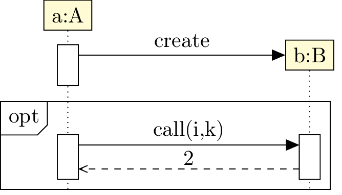
5.4.1 Informations of a fragment

The type option allows to set the keyword on the top left corner: opt, alt, loop, par, assert, …The default value is opt.

The label option allows to set information such as the condition for a opt fragment:

 \begin{tikzpicture}  \begin{umlseqdiag}  \umlobject[class=A]{a}  \umlcreatecall[class=B]{a}{b}  \begin{umlfragment}[type=alt, label=i>5, inner xsep=2]  \begin{umlcall}[op={call(i,k)}, dt=7, return=2]{a}{b}  \end{umlcall}  \end{umlfragment}  \end{umlseqdiag}  \end{tikzpicture}

pict

The inner xsep option allows to shift type and label to the left. The default value is 1 and its unit is ex.

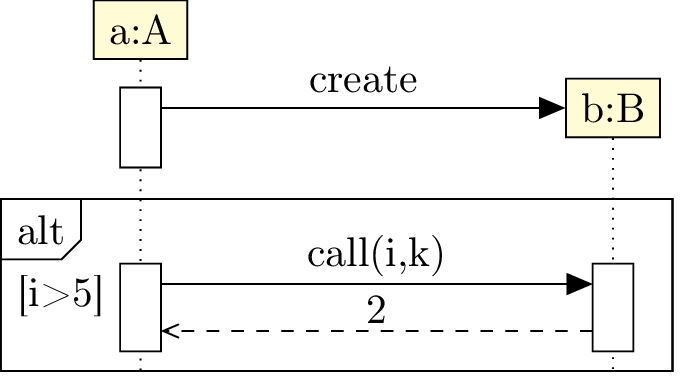
5.4.2 Name of a fragment

You can give a name to a combined fragment with the name option. It can be useful when you want to attach a note on a fragment:

 \begin{tikzpicture}  \begin{umlseqdiag}  \umlobject[class=A]{a}  \umlcreatecall[class=B]{a}{b}  \begin{umlfragment}[type=alt, label=i>5, name=alt, inner xsep=2]  \begin{umlcall}[op={call(i,k)}, dt=7, return=2]{a}{b}  \end{umlcall}  \end{umlfragment}  \umlnote[x=2, y=-5]{alt}{note on alt fragment}  \end{umlseqdiag}  \end{tikzpicture}

pict

5.4.3 To define regions of a fragment

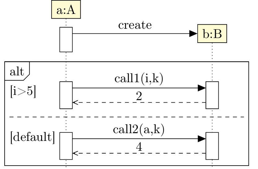
Let’s take a alt fragment. It represents a switch-case instruction block. To represent each case, you need to set regions in the fragment. For this purpose, you can use the umlfpart command:

 \begin{tikzpicture}  \begin{umlseqdiag}  \umlobject[class=A]{a}  \umlcreatecall[class=B]{a}{b}  \begin{umlfragment}[type=alt, label=i>5, inner xsep=5]  \begin{umlcall}[op={call1(i,k)}, dt=7, return=2]{a}{b}  \end{umlcall}  \umlfpart[default]  \begin{umlcall}[op={call2(a,k)}, return=4]{a}{b}  \end{umlcall}  \end{umlfragment}  \end{umlseqdiag}  \end{tikzpicture}

pict

5.5 To change preferences

Thanks to the tikzumlset command, you can set colors for calls, fragments and objects:

text:
allows to set the default text color (=black by default),
draw:
allows to set the default color of edges and arrows (=black by default),
fill object:
allows to set the default background color of objects (=yellow !20 by default),
fill call:
allows to set the default background color for calls (=white by default),
fill fragment:
allows to set the default background color for fragments (=white by default),
font:
allows to set the default font style (=\small by default),
object stereo:
allows to set the default font style (=object by default),
call dt:
allows to set the default font style (=auto by default),
call padding:
allows to set the default font style (=2 by default),
call type:
allows to set the default font style (=synchron by default),
fragment type:
allows to set the default font style (=opt by default),
fragment inner xsep:
allows to set the default font style (=1 by default),
fragment inner ysep:
allows to set the default font style (=1 by default),
create call dt:
allows to set the default font style (=4 by default)

You can also use the options text, draw and fill on a particular element, as in the example of introduction.

There is an exception: umlcreatecall. The options text, draw and fill set the colors of the call, whereas options text obj, draw obj and fill obj set the colors of the object.

 \begin{tikzpicture}  \begin{umlseqdiag}  \umlactor[class=A]{a}  \umlcreatecall[class=B, draw obj=green!70!black, fill obj=green!20, draw=blue!70]{a}{b}  \end{umlseqdiag}  \end{tikzpicture}

pict

5.6 Examples

5.6.1 Example from introduction, step by step

Definition of objects
 \begin{umlseqdiag}  \umlactor[class=A]{a}  \umldatabase[class=B, fill=blue!20]{b}  \umlmulti[class=C]{c}  \umlobject[class=D]{d}
 \end{umlseqdiag}  \end{tikzpicture}

pict

Definition of the call opa and its components
 \begin{umlseqdiag}  \umlactor[class=A]{a}  \umldatabase[class=B, fill=blue!20]{b}  \umlmulti[class=C]{c}  \umlobject[class=D]{d}
 \begin{umlcall}[op=opa(), type=synchron, return=0]{a}{b}
 \begin{umlcall}[op=opb(), type=synchron, return=1]{b}{c}
 \begin{umlcall}[op=opc(), type=asynchron, fill=red!10]{c}{d}  \end{umlcall}  \begin{umlcall}[type=return]{c}{b}  \end{umlcall}
 \begin{umlcall}[op=opd(), type=synchron, return=3]{c}{d}  \end{umlcall}
 \end{umlcall}
 \end{umlseqdiag}  \end{tikzpicture}

pict

Definition of the calls following the construction of E
 \begin{umlseqdiag}  \umlactor[class=A]{a}  \umldatabase[class=B, fill=blue!20]{b}  \umlmulti[class=C]{c}  \umlobject[class=D]{d}  \begin{umlcall}[op=opa(), type=synchron, return=0]{a}{b}
 \begin{umlcall}[op=opb(), type=synchron, return=1]{b}{c}
 \begin{umlcall}[op=opc(), type=asynchron, fill=red!10]{c}{d}  \end{umlcall}  \begin{umlcall}[type=return]{c}{b}  \end{umlcall}
 \begin{umlcall}[op=opd(), type=synchron, return=3]{c}{d}  \end{umlcall}
 \end{umlcall}
 \begin{umlcallself}[op=ope(), type=synchron, return=4]{b}
 \begin{umlcall}[op=opf(), type=synchron, return=5]{b}{c}  \end{umlcall}
 \end{umlcallself}
 \end{umlcall}  \umlcreatecall[class=E, x=8]{a}{e}
 \begin{umlcall}[op=opg(), name=test, type=synchron, return=6, dt=7, fill=red!10]{a}{e}  \umlcreatecall[class=F, stereo=boundary, x=12]{e}{f}  \end{umlcall}  \begin{umlcall}[op=oph(), type=synchron, return=7]{a}{e}  \end{umlcall}
 \end{umlcall}

pict

Definition of fragments
 \begin{umlseqdiag}  \umlactor[class=A]{a}  \umldatabase[class=B, fill=blue!20]{b}  \umlmulti[class=C]{c}  \umlobject[class=D]{d}  \begin{umlcall}[op=opa(), type=synchron, return=0]{a}{b}
 \begin{umlfragment}
 \begin{umlcall}[op=opb(), type=synchron, return=1]{b}{c}
 \begin{umlfragment}[type=alt, label=condition, inner xsep=8, fill=green!10]
 \begin{umlcall}[op=opc(), type=asynchron, fill=red!10]{c}{d}  \end{umlcall}  \begin{umlcall}[type=return]{c}{b}  \end{umlcall}
 \umlfpart[default]
 \begin{umlcall}[op=opd(), type=synchron, return=3]{c}{d}  \end{umlcall}
 \end{umlfragment}
 \end{umlcall}
 \end{umlfragment}  \begin{umlfragment}
 \begin{umlcallself}[op=ope(), type=synchron, return=4]{b}
 \begin{umlfragment}[type=assert]
 \begin{umlcall}[op=opf(), type=synchron, return=5]{b}{c}  \end{umlcall}
 \end{umlfragment}
 \end{umlcallself}
 \end{umlfragment}
 \end{umlcall}  \umlcreatecall[class=E, x=8]{a}{e}
 \begin{umlfragment}
 \begin{umlcall}[op=opg(), name=test, type=synchron, return=6, dt=7, fill=red!10]{a}{e}  \umlcreatecall[class=F, stereo=boundary, x=12]{e}{f}  \end{umlcall}  \begin{umlcall}[op=oph(), type=synchron, return=7]{a}{e}  \end{umlcall}
 \end{umlfragment}
 \end{umlseqdiag}  \end{tikzpicture}

pict

5.7 Known bugs and perspectives

  1. When you define a fragment on a set of calls just after a constructor call, the automatic shift does not work. You have to use the dt with a value greather than 7 to the first call inside the fragment.
  2. The automatic placement of objects with a multiple of 4 is not very convenient. A shift of 4 relatively to the last object drawn should be better.
  3. You can not give arguments to constructor calls.
  4. You can not force the drawing of the activity area of a "non working" object.
     \begin{tikzpicture}  \begin{umlseqdiag}  \umlactor[no ddots]{user}  \umlobject[class=A]{a}  \umlobject[class=B]{b}  \begin{umlcall}{a}{b}  \end{umlcall}  \end{umlseqdiag}  \end{tikzpicture}

    pict

    But you can lengthen lifelines thanks to umlsdnode command:

     \begin{tikzpicture}  \begin{umlseqdiag}  \umlactor[no ddots]{user}  \umlobject[class=A]{a}  \umlobject[class=B]{b}  \begin{umlcall}{a}{b}  \end{umlcall}  \umlsdnode[dt=10]{user}  \umlsdnode[dt=4]{a}  \end{umlseqdiag}  \end{tikzpicture}

    pict