Chapter 3
Use case diagrams

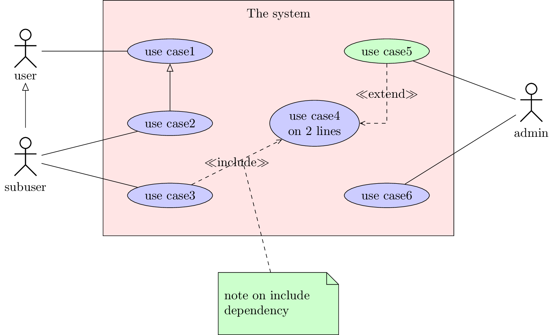
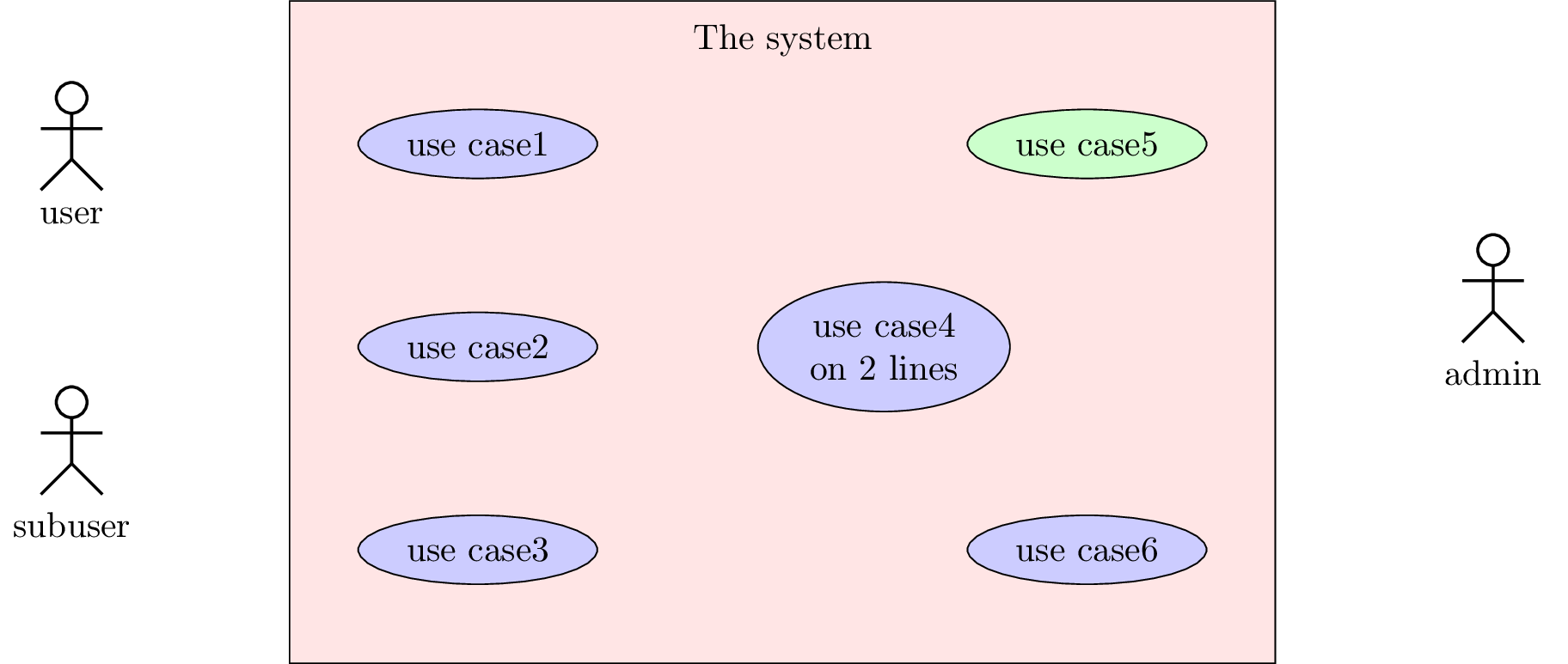
Here is an example of use case diagram you can draw:

pict

We will see how to define the four constitutive elements of such a diagram: the system, the actors, the use cases and the relations.

3.1 To define a system

A system is defined by the
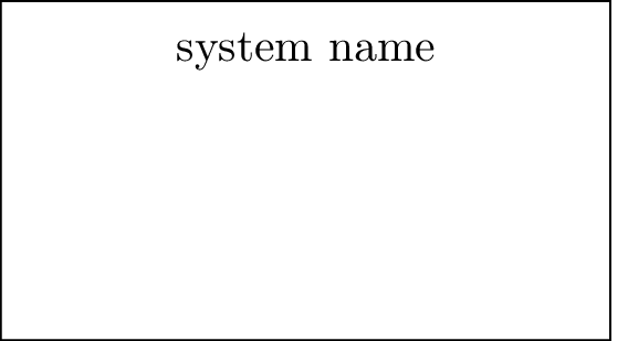
 umlsystem environment:

 \begin{tikzpicture}  \begin{umlsystem}[x=0, y=0]{system name}    \end{umlsystem}  \end{tikzpicture}

pict

Both options x and y allow to place the system in the picture. The default value is 0. Inside this environment, you will define use cases, whereas outside, you will define actors.

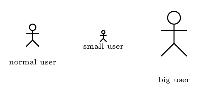
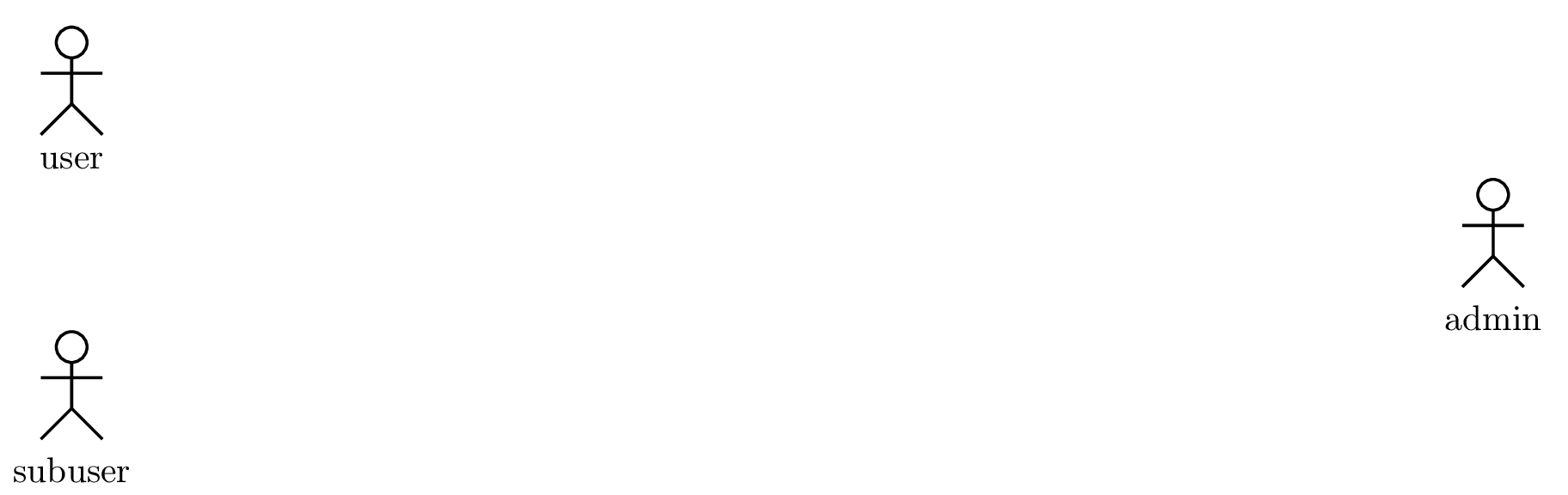
3.2 To define an actor

You can define an actor with the
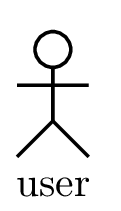
 umlactor command:

 \begin{tikzpicture}  \umlactor[x=0, y=0]{user}  \end{tikzpicture}

pict

Both options x and y allow to place the actor in the picture. The default value is 0. You can change dimensions of the actor symbol with the scale option. It also adapts position of the label below:

 \begin{tikzpicture}  \umlactor{normal user}  \umlactor[x=2, scale=0.5]{small user}  \umlactor[x=4, scale=2]{big user}  \end{tikzpicture}

pict

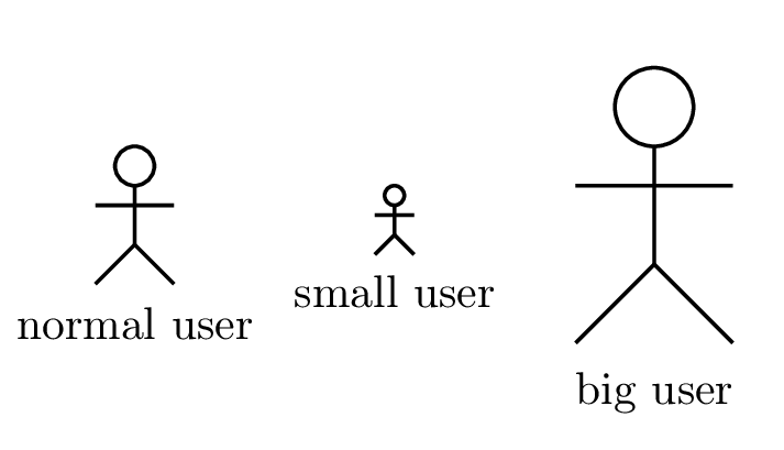
The actor symbol size is defined according to the font size (ex unit), whereas the distance between the symbol and the label is in cm. You can adjust it if you need with the below option (0.5cm by default).

 \tikzumlset{font=\tiny}  \begin{tikzpicture}  \umlactor{normal user}  \umlactor[x=2, scale=0.5, below=0.1cm]{small user}  \umlactor[x=4, scale=2]{big user}  \end{tikzpicture}

pict

Every TikZ option dedicated to nodes can be used here, see section 2.5 for details.

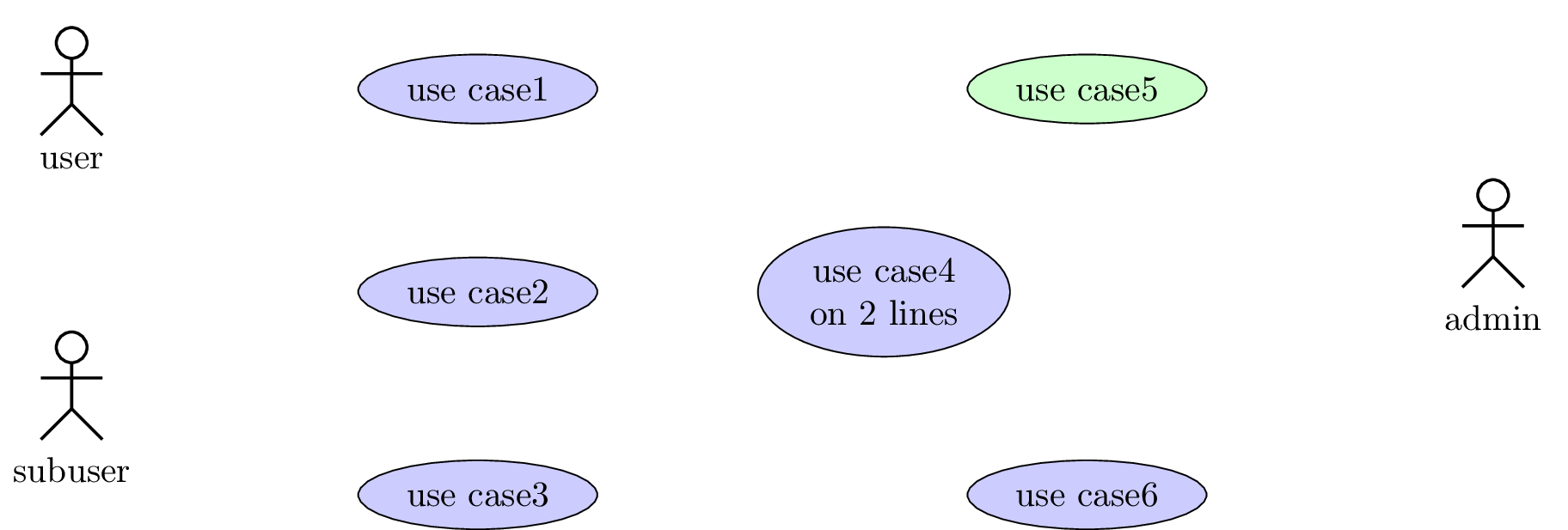
3.3 To define a use case

You can define a use case with the
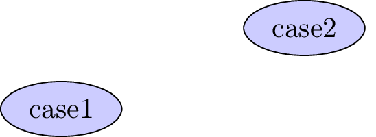
 umlusecase command:

 \begin{tikzpicture}  \umlusecase[x=0, y=0]{case1}  \umlusecase[x=3, y=1]{case2}  \end{tikzpicture}

pict

Both options x and y allow to place the use case in the picture or in the container system. The default value is 0. The text argument is the label of the use case. The node representing the use case has a default name, based on a global counter, that is like usecase-17. For pratical reasons, you can rename it thanks to the name option.

Furthermore, you can set the witdh of the use case with the width option.

Every TikZ option dedicated to nodes can be used here, see section 2.5 for details.

Now, we can talk about relations between use cases, systems and actors.

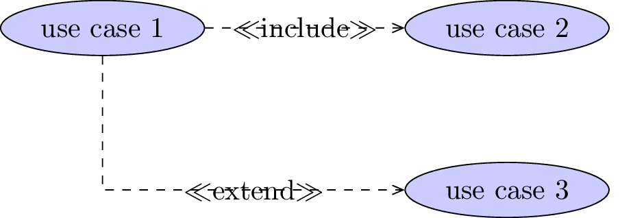
3.4 To define a relation

Relations in a user case diagram are of 4 categories:

anchor1, anchor2, anchors, arm1, arm2, weight, geometry (only for umlinclude and umlextend), and pos stereo options are available here.

 \begin{tikzpicture}  \umlusecase[name=case1]{use case 1}  \umlusecase[x=5, name=case2]{use case 2}  \umlusecase[x=5, y=-2, name=case3]{use case 3}    \umlinclude{case1}{case2}  \umlVHextend[pos stereo=1.5]{case1}{case3}  \end{tikzpicture}

pict

3.5 Advanced features for positioning

umlactor and umlusecase can accept every option key defined for nodes in TikZ . In this section, you will see how some of them can be used for advanced features.

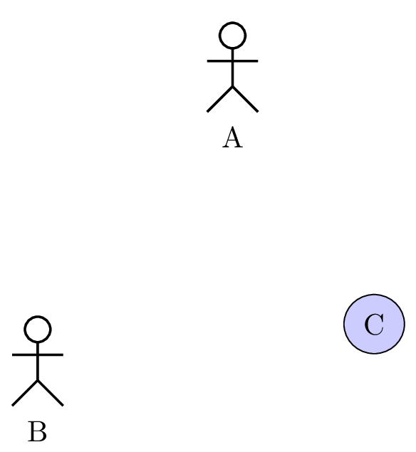
3.5.1 Horizontal and vertical alignment

In a use case diagram, cases and actors have different width and height. For a graphical purpose, you may want to align them horizontally or vertically. Let’s take the following example:

 \begin{tikzpicture}  \umlactor{A}  \umlactor[x=-2, y=-3]{B}  \umlusecase[x=2, y=-3]{C}  \end{tikzpicture}

pict

The y coordinate defines the center of the case or actor node. It will be better in this example to have actpr B and case C top-aligned. A solution is to define manually the y value for C, but it is not very convenient. You may prefer use the anchor option. If you specify anchor=north, the y coordinate will define the top center anchor of the node, instead of the center. You may take a look at the differences between both codes.

 \begin{tikzpicture}  \umlactor{A}  \umlactor[x=-2, y=-2, anchor=north]{B}  \umlusecase[x=2, y=-2, anchor=north]{C}  \end{tikzpicture}

pict

You can notice there is still mis-alignement. It is because an actor node is elliptical and hidden.

In a similar way, you may use anchor=east to right align classes, anchor=west to left align classes or anchor=south to bottom align classes.

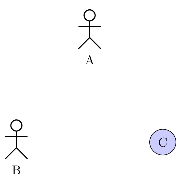
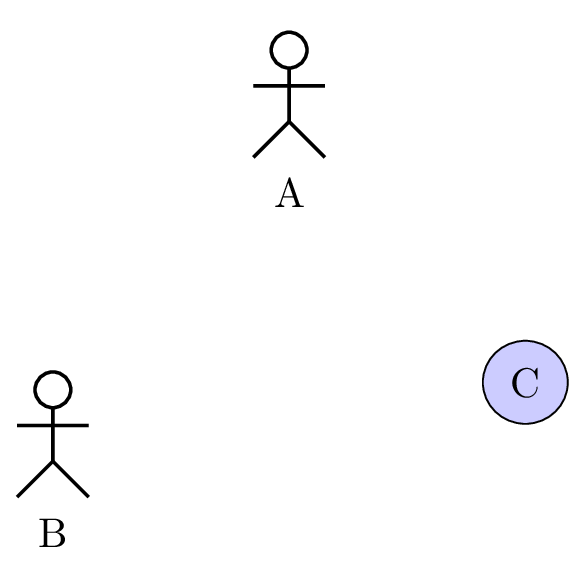
3.5.2 Relative positioning

Using the x-y coordinate system may be very hard in big diagrams, when you have to change position of elements in order to fit the diagram to the page. Relative positioning may be useful in this case, namely advanced syntax of options above, left, below, right, above left, below left, below right and above right provided by the TikZ library positioning.

Let’s take the previous example, you can define B by its cordinates (-2,-2) or by saying that B is 2cm below and 2cm left of A. You can also define C by saying it is 4cm right of B. Notice that because of the top alignment of B and C, the latter is defined 4cm right of B.north.

 \begin{tikzpicture}  \umlactor{A}  \umlactor[below left=2cm and 2cm of A, anchor=north]{B}  \umlusecase[right=4cm of B.north, anchor=north]{C}  \end{tikzpicture}

pict

3.6 To change preferences

With the tikzumlset command, you can change default colors for use cases, systems, actors and relations:

text:
allows to set the text color (=black by default),
draw:
allows to set the edge colors (=black by default),
fill usecase:
allows to set the background color for use cases (=blue!20 by default),
fill system:
allows to set the background color for systems (=white by default),
font:
allows to set the font style (=\small by default).
actor below:
allows to set the space between actor symbol and text (=0.5cm by default)

You can also use text, draw and fill options on a particular element to change its colors, as shown in the introduction example.

3.7 Examples

3.7.1 Example from introduction, step by step

Definition of actors
 \umlactor{user}  \umlactor[y=-3]{subuser}  \umlactor[x=14, y=-1.5]{admin}

pict

Definition of use cases

We also show here the use of the fil option.

 \umlusecase{use case1}  \umlusecase[y=-2]{use case2}  \umlusecase[y=-4]{use case3}  \umlusecase[x=4, y=-2, width=1.5cm]{use case4 on 2 lines}  \umlusecase[x=6, fill=green!20]{use case5}  \umlusecase[x=6, y=-4]{use case6}
 \umlactor{user}  \umlactor[y=-3]{subuser}  \umlactor[x=14, y=-1.5]{admin}

pict

Definition of the system

As the system is a box used as a new coordinate system, we have to change coordinates of use cases.

 \begin{umlsystem}[x=4, fill=red!10]{The system}
 \umlusecase{use case1}  \umlusecase[y=-2]{use case2}  \umlusecase[y=-4]{use case3}  \umlusecase[x=4, y=-2, width=1.5cm]{use case4 on 2 lines}  \umlusecase[x=6, fill=green!20]{use case5}  \umlusecase[x=6, y=-4]{use case6}
 \end{umlsystem}
   \umlactor{user}  \umlactor[y=-3]{subuser}  \umlactor[x=14, y=-1.5]{admin}

pict

Definition of relations and of the note

You will notice here the use of the name option to ensure the definition of the note, and its interest for use cases, in order to ignore the order of their definition, as shown in the following example:

 \begin{umlsystem}[x=4, fill=red!10]{The system}  \umlusecase{use case1}  \umlusecase[y=-2]{use case2}  \umlusecase[y=-4]{use case3}  \umlusecase[x=4, y=-2, width=1.5cm]{use case4 on 2 lines}  \umlusecase[x=6, fill=green!20]{use case5}  \umlusecase[x=6, y=-4]{use case6}  \end{umlsystem}    \umlactor{user}  \umlactor[y=-3]{subuser}  \umlactor[x=14, y=-1.5]{admin}
   \umlinherit{subuser}{user}  \umlassoc{user}{usecase-1}  \umlassoc{subuser}{usecase-2}  \umlassoc{subuser}{usecase-3}  \umlassoc{admin}{usecase-5}  \umlassoc{admin}{usecase-6}  \umlinherit{usecase-2}{usecase-1}  \umlVHextend{usecase-5}{usecase-4}  \umlinclude[name=incl]{usecase-3}{usecase-4}    \umlnote[x=7, y=-7]{incl-1}{note on include dependency}

pict